
Use calculator nowRead the voltage drop guide ↓
Voltage Drop Calculator + Wire Size Guide (DC & AC)
Use the voltage drop calculator below to find your voltage loss — and the right wire size to fix it — for any DC or AC circuit: solar, battery, or general wiring. Enter your wire material, size, one-way length, and load, and it returns the voltage drop in volts, the drop as a percentage, and the voltage that actually reaches the far end of the run.
The long DC run from your panels down to the inverter — this is where voltage drop matters most, especially on ground-mount arrays with long conductor runs. Uses solar string logic: module Isc × parallel strings × 1.25 for current, and your actual string voltage — not the inverter's AC output breaker.
If each string is run separately back to the inverter, enter 1. If multiple strings are combined before this run, enter the number of combined strings. Do not enter the total number of strings in the system unless all of those strings are carried on this same wire run.
Calculated: 13.5 A × 1 string × 1.25 = 16.88 A.
For DC solar runs, current is based on module Isc and the number of parallel strings carried by this wire run. It is not based on the inverter's AC breaker size.
Common solar string voltage estimate. Confirm against your actual panel and inverter design before finalizing wire size.
Enter the ONE-WAY run length — the calculator accounts for the return conductor automatically.
Using 1 string from the load-current section above — each needs its own PV+ / PV− pair for the run; one ground covers them.
Circuit wire: 10 AWG copper — from your selection above.
Rough retail estimate — wire prices move with the copper market. Type your supplier's quote for an exact total.
Circuit conductors only — equipment ground wire and conduit are separate line items on a real install.
💡 On long runs, aluminum (upsized a gauge or two to hit the same drop) often costs a fraction of copper — flip the material above to compare.
Formula & assumptions (for review)
Vd = (M × K × I × L) / CM- M (phase multiplier) = 2 for DC (two conductors, out & back)
- K = 12.9 ohm·cmil/ft for copper at ~75 °C
- I = 16.875 A · L = 150 ft (one-way) · CM = 10,380 circular mils · source = 400 V
- Vd% = Vd ÷ source × 100. Voltage at load = source − Vd.
This is for educational purposes only. Please consult with an experienced contractor or engineer to confirm the final requirements for your wire size and gauge.
What is voltage drop?
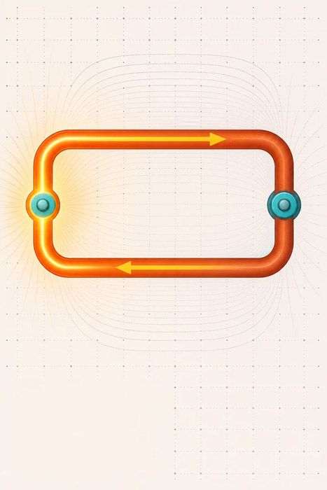
Voltage drop is the voltage lost as current travels through the resistance of a conductor. Every wire has some resistance, so by the time electricity reaches the far end of a run, it arrives at a slightly lower voltage than it left with. That lost voltage turns into heat — and in a solar array, into lost kilowatt-hours.
Four things control how much you lose:
- Wire size — bigger wire has less resistance, so less drop.
- Wire length — longer run, more resistance, more drop (a direct, one-to-one relationship).
- Current (load) — the more amps you push, the more you lose.
- Material — copper drops less than aluminum for the same size.
You'll also see voltage drop called voltage loss, line loss, or wire loss — same thing. The goal when you design any circuit is to keep that loss small enough that your equipment gets the voltage it needs and your array delivers the output it should.
What counts as acceptable voltage drop?
This is the question the calculator is really answering — and it's widely mis-stated online, so here's the practical planning version most homeowners should understand.
The National Electrical Code (NEC / NFPA 70) does not make voltage drop a hard, enforceable requirement for most circuits. The guidance lives in Informational Notes — which NEC 90.5 defines as explanatory material that is not enforceable as a requirement — attached to NEC 210.19 (branch circuits) and NEC 215.2 (feeders). The thresholds they recommend:
| Circuit | Recommended max voltage drop |
|---|---|
| A single branch circuit or feeder | 3% |
| Total (feeder + branch circuit combined) | 5% |
For solar, the industry best practice is tighter than code:
| Solar circuit | Target voltage drop |
|---|---|
| DC array → inverter (PV source/output) | 2% or less |
| AC inverter → main panel | ~1% (and watch voltage rise — see below) |
Why go tighter than 3% on a solar DC run? Because that drop is production you never get back, on every sunny day, for the 25-year life of the array. Shaving a run from 3% down to under 2% is often just one wire size up — cheap insurance against years of lost kilowatt-hours. A properly designed system should come in comfortably under 2%.
Bottom line: Under 3% keeps you aligned with NEC guidance on general wiring. Under 2% is the mark to hit on a solar DC run.

How to use the voltage drop calculator
Enter these six inputs:
- Material — copper or aluminum. Copper drops less voltage; aluminum is cheaper and works fine if you size up.
- Wire size — the gauge (AWG) or metric area (mm²). Larger wire = less voltage drop.
- Phase — pick DC for solar PV and battery circuits, single-phase for standard residential AC, or three-phase to match a commercial utility service. The calculator applies the correct multiplier for each.
- 1-way circuit length — the distance in feet one way: array to inverter, or inverter to service panel. (The calculator automatically doubles it to account for the return conductor — don't pre-double it yourself.)
- Load — the current in amps flowing through the circuit. For a solar DC source circuit, use short-circuit current (Isc) × 1.25, the NEC continuous-duty factor. For an AC circuit, use the inverter's maximum continuous output current.
- Source voltage — the nominal voltage of the circuit. 240V is standard for a U.S. residential service panel; a DC solar string may be much higher.
You get four outputs:
- Voltage Drop (V) — the volts lost over the run.
- Voltage Drop % — that loss as a percentage of source voltage. This is the number you compare against the 2–3% targets above.
- Voltage at Load End — the voltage actually arriving at the far end after the drop.
- CMA of Conductor — the Circular Mil Area, the cross-sectional area of the wire size you selected.
How to size wire with it: start with a wire size, read the drop %, and bump the size up until the percentage lands under your target. Two minutes of this beats guessing — and beats buying the wrong wire.
How to calculate voltage drop by hand (the formula)
Want to check the math or work it out without the tool? Here's the exact formula the calculator uses — the standard NEC-aligned "K method."
DC and single-phase AC:
`` Vd = (2 × K × I × L) / CM ``
Three-phase AC (swap the 2 for √3):
`` Vd = (1.732 × K × I × L) / CM ``
Where:
- Vd = voltage drop, in volts
- K = conductor constant (approx. resistivity at 75 °C): 12.9 for copper, 21.2 for aluminum
- I = current, in amps
- L = one-way length of the run, in feet
- CM = circular-mil area of the conductor (e.g. 10 AWG ≈ 10,380 CM, 6 AWG ≈ 26,240 CM)
To get the percentage, divide by your source voltage:
`` Voltage Drop % = (Vd / Source Voltage) × 100 ``
Two things trip up by-hand calculations: forgetting the 2 × (or 1.732 ×) that accounts for current traveling out and back, and using resistance at room temperature. Conductor resistance climbs about 0.4% per °C, so a hot conductor drops more than a cold one — the 75 °C K-values above bake in a realistic operating temperature.
Worked example: a ground-mount PV string run
Here's a realistic ground-mount case — a long DC string run from an array out in the yard back to the inverter, where distance is the whole problem:
- 10 panels in series
- Panel Vmp: 41 V → string operating voltage ≈ 410 V
- Module Isc: 13.5 A
- Parallel strings carried by this wire run: 1
- Design current: 13.5 A × 1 string × 1.25 = 16.88 A
- One-way distance: 150 ft
Run the drop for 10 AWG copper (10,380 CM):
Vd = (2 × 12.9 × 16.88 × 150) / 10,380 ≈ 6.29 V → 6.29 / 410 × 100 ≈ 1.5% — comfortably under the 2% solar target.
Step up to 8 AWG copper (16,510 CM) and the drop falls to about 3.96 V, or ~1.0% — extra headroom for a modest cost bump on a long run.
Voltage drop by wire size (quick reference)
A rough guide to how much conductor you're working with at each size. Always confirm with the calculator for your exact current, length, and voltage — this is a starting point, not a substitute for the math.
| Wire size | Circular mils | Approx. metric | Relative resistance | Best for |
|---|---|---|---|---|
| 14 AWG | 4,110 | ~2.5 mm² | Highest | Short, low-current runs |
| 12 AWG | 6,530 | ~4 mm² | High | Small circuits |
| 10 AWG | 10,380 | ~6 mm² | Moderate | Common PV string / branch |
| 8 AWG | 16,510 | ~10 mm² | Lower | Longer PV / battery runs |
| 6 AWG | 26,240 | ~16 mm² | Low | Higher-current battery runs |
| 4 AWG | 41,740 | ~25 mm² | Very low | Long, high-current runs |
The pattern: every step up in wire size roughly cuts voltage drop, so long or high-current runs reward bigger conductors. One caution — this table sizes wire for voltage drop only. Always cross-check that your chosen wire is also rated for the circuit's ampacity (its safe current-carrying limit). Voltage drop tells you how efficient the run is; ampacity tells you whether it's safe. You have to satisfy both.

DC vs AC, single-phase vs three-phase, AWG vs mm²
The physics is the same across all of these; only the multiplier or the units change:
- DC (solar PV, batteries): use the
2 ×formula. This is what most people mean by a DC voltage drop calculator. - Single-phase AC (standard homes): same
2 ×formula. - Three-phase AC (commercial): use
1.732 ×(√3) instead of 2. - Metric (mm²) instead of AWG: identical relationship — larger cross-sectional area means lower resistance and less drop. Select the metric wire size and the calculator handles the conversion. (Rough bridge: 4 mm² ≈ 12 AWG, 6 mm² ≈ 10 AWG, 10 mm² ≈ 8 AWG.)
Whether you're running a cable for a PV string, a battery bank, or a general branch circuit, the calculator above covers it — just match the phase and units to your job.
Voltage drop vs voltage rise in solar
On a grid-tie system, there's a mirror image of voltage drop worth knowing about: voltage rise.
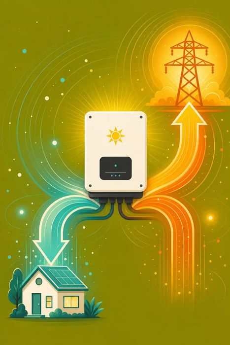
When your inverter exports power, current flows from the inverter toward the grid — the opposite direction of a normal load. That pushes the voltage at the inverter's terminals slightly higher than the grid voltage. If the rise is too large, the inverter sees an over-voltage condition and throttles its output or trips offline to protect itself — costing you production on your sunniest, highest-output days.
The fix is the same math you just used: size the AC conductors so the rise stays low (aim for ~1% or less on the inverter-to-panel run). Any circuit that carries current can drop or rise voltage — so the wire-sizing discipline that controls drop also controls rise.
How to reduce voltage drop
If the calculator hands you a number that's too high, here's how to bring it down, in rough order of impact:
- Shorten the run. Put components close together. Length has a one-to-one effect on drop, so halving the distance halves the loss. This is the cheapest fix — plan your equipment layout before you buy wire.
- Go up a wire size. Larger conductor = less resistance = less drop. Often one size up is all it takes to clear the target.
- Raise the system voltage. Higher voltage means lower current for the same power, and lower current means less drop. On long solar runs, use higher-voltage equipment and larger panel strings (with a string inverter) to overcome distance.
- Choose copper over aluminum on critical runs, or size the aluminum up one to two gauges to compensate.
Design the circuit around these levers before you pull wire, and voltage drop stops being a problem you fix later and becomes a number you hit on purpose.
Let us design the wiring for you
Feeling stuck on system design? You don't have to get the wire sizing perfect on your own.
Every complete system Unbound Solar sells includes an electrical wiring diagram engineered to minimize voltage drop and meet code — so your components are matched, your runs are sized, and your array performs the way it should from day one.
- Explore the Solar Information Hub for the rest of the design picture, from panels to inverters.
- Size your project with our solar cost estimator, off-grid load calculator, or battery bank sizing calculator.
- Shop solar panels and wire, breakers & electrical components, or browse complete solar kits that arrive pre-engineered.
- Or request a free system design and talk to a real designer.
Get a free estimate in under a minute. See exactly what your system will cost — plus the sizing metrics behind it — in about 30 seconds. Free, no obligation. Get my free report →

Questions people actually ask
Straight answers, sourced from real searches.
Use Vd = (2 x K x I x L) / CM, where K is 12.9 for copper or 21.2 for aluminum, I is current in amps, L is the one-way run length in feet, and CM is the wire's circular-mil area. Divide the result by source voltage and multiply by 100 for the percentage. The 2 accounts for current flowing out and back; for three-phase, use 1.732 instead of 2.
The NEC's Informational Notes (following 210.19 for branch circuits and 215.2 for feeders) recommend no more than 3% on a single branch circuit or feeder, and 5% total from source to load. These are recommendations, not enforceable rules in most jurisdictions. For solar, best practice is tighter: 2% or less on the DC array-to-inverter run and about 1% on the AC side to protect production.
Yes. Voltage drop is directly proportional to length, so doubling the one-way run doubles the drop. Shortening the run or going up a wire size are the fastest fixes.
Copper has lower resistance, so it drops less voltage for the same size and length. Aluminum works if you go up one or two wire sizes to compensate, which can be cheaper on long, high-current runs.
Single-phase AC uses the same 2x formula as DC. Three-phase uses 1.732 (the square root of 3) instead of 2: Vd = (1.732 x K x I x L) / CM. Select the matching phase in the calculator and it applies the right multiplier.
Yes. The physics is identical: larger cross-sectional area means less resistance and less drop. Select the metric wire size and the calculator handles the conversion. As a rough bridge, 4 mm2 is near 12 AWG, 6 mm2 near 10 AWG, and 10 mm2 near 8 AWG.
It depends on your current, distance, and voltage. Enter them in the calculator and increase the wire size until the drop reads under your target (2% for a solar DC run, 3% for general wiring). Raising system voltage lets you use smaller wire over long runs.
Voltage rise is the flip side of voltage drop on grid-tie AC circuits: when the inverter exports power, current flows toward the grid and pushes voltage at the inverter's terminals above grid voltage. Too much rise makes the inverter throttle or trip offline, so the same wire-sizing math keeps it low, aiming for about 1%.
Ready for the next step?
Everything sized, matched, and code-ready — designed for self-install.